Dream Team: Torque Sensor Integrated In Coupling
by Dr. Wilfried Krimmel
Downloads
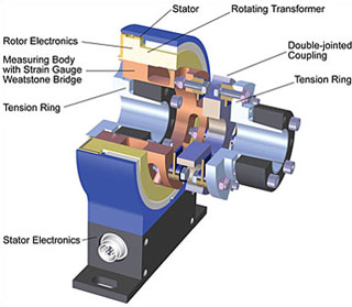
- Figure 1: Setup of Torque Sensor DR-2554
The natural frequency of the mechanical construction of a torque measuring device appertains to the important dynamic features of the testing equipment layout. The new torque sensor DR-2554 succeeded in increasing this natural frequency beyond factor 3, whereby dynamic measurements with even higher accuracy become possible. This was achieved by a consistent advancement of the torque sensors and a closely cooperation with a coupling manufacturer. In addition, great flexibility arose in adaptation possibilities at concurrent short design.
In torque measurement technology, dynamic measurements are carried out very frequently. Here it is to be differentiated whether the excitation of the torque occurs periodically, or whether it is a single procedure. Typical periodic torque courses can be watched at piston engines, presses, tooth shocks in gears, AC-induction motors etc. Torque courses at start-up and brake procedures represent non-periodic excitations.
In case of periodic courses, the torque sensor with the parts mounted, shows the characteristics of a mechanical oscillator with an increase of the amplitude in the natural frequency. In consequence of this, the excitation frequency should not be the same as the natural frequency of the layout because due to the low damping of the testing device, intense increases of the torque must be reckoned. Thus, torques can arise at an excitation amplitude close to the rated torque which will damage the parts in the shaft assembly. However, a fast pass-through of the natural frequency is absolutely possible, because the system does not have the time to allow a dangerous rise of the amplitude. Further it should be noticed that by means of a fourier series, each periodic excitation can be fragmented in discrete sinusoidal frequency portions. Hereby the frequencies of the sinus oscillations are a multiple of the basic frequency.
The jump function, for instance, represents non-periodic signals. A jumpwise change in the torque causes an oscillation with the natural frequency of the mechanical setup. The amplitude of the oscillation is depending on the damping and can accept maximally the twofold amount of the jump amplitude.
Thus, adulterations of the measuring signal due to the natural frequencies of the mechanical setup are to be expected because the testing setup acts like a mechanical low-pass filter. Below the natural frequency, the torque amplitudes are measured very well. In the resonance range, intense increases have to be expected and at larger torque amplitudes the damage of parts is to be reckoned. Above the resonance range, smaller measured values are obtained. In practice therefore, a preferably high natural frequency of the sensor is desired.
Determination of the Natural Frequency
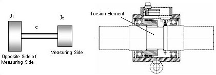
- Figure 2: Model for 2 Mechanical Mass Oscillators (left side), Typical Setup of a Torque Sensor (right side)
In the simplest case, as represented in picture 2, a torque sensor can be considered as a mechanical oscillator and a torsion spring with a mass attached on each end.
The measuring side and the drive side (opposite side of the measuring side) are to be differentiated. The mass moment of inertia J of a body represents its resistance to rotational accelerations. The torsion body which mainly contributes to the elastic and resilient effect is located between the two inertial masses. The spring constant c is the decisive measure for the torsion body. For the approximate computation of the natural frequency, the masses are assigned to both sides of the torsion element.
Thus, the torsion natural frequency f of the layout is computed according:
The equation shows: The higher the spring constant, the higher becomes the natural frequency of the testing layout. Inversely: The smaller the moment of inertia , the higher becomes the natural frequency. A good torque sensor therefore has a preferably stiff mechanical construction and low masses. Since the torque sensor is installed into the shaft assembly via torsionally stiff couplings, it is suggestive to consider the applied couplings with regard to the natural frequency.
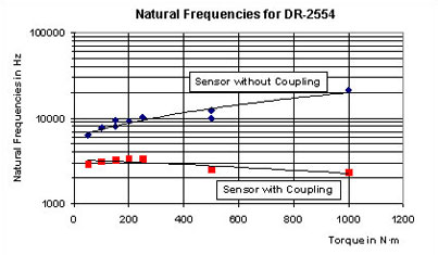
- Figure 3: Natural Frequencies for Sensors with and without Coupling
Torque Sensor DR-2554 with Integrated Double-Jointed Coupling
At first, the torque sensor newly designed by Lorenz Messtechnik GmbH was calculated without couplings and clamping-parts. Thereupon the recommended combination of clamping hub at the drive side and double-jointed coupling at the measuring side was calculated. On picture 3 the results are represented graphically.
For comparison, a calculation was carried out in combination of a conventional setup, consisting of a torque sensor between two single-jointed couplings. The most important data are summarized in following table 1.
| Sensor Type | Sensor without Coupling | Sensor with Coupling |
|---|---|---|
| Table 1: Comparison of the Natural Frequencies of a Conventional Sensor and DR-2554 | ||
| Conventional Sensor | 1 kHz … 6 kHz | 300 Hz … 1 kHz |
| DR-2554 | 6 kHz … 20 kHz | 2,3 kHz … 3,3 kHz |
The comparison shows that the DR-2554 has a more than threefold higher natural frequency than a conventional torque sensor. This applies for the sensor as well as for the combination of torque sensor with couplings. Thus, for dynamic measurements the new sensor shifts the necessary high natural frequency to considerably higher values than conventionally constructed torque sensors.
Setup of the Torque Sensor
The sensor consists of a stationary part, the stator, and a rotating part, the rotor; see figure 1.
The stator electronics, the coils necessary for the signal transmission and the connector for the electrical connection of the sensor are located in the stator. Here, you can also find the optional speed sensor. The free-floating rotor without bearings consists of the measuring body on which the Wheatstone-bridge-circuit with strain gauges is applied. The rotating electronics and the rotating part of the rotating transformer is attached at the measuring body. A tension ring is attached on the left side of the measuring body and the double-jointed coupling is attached on the right side (see figure 1).
By the free-floating bearing-free design of the testing equipment layout no additional bearing friction of the torque sensor has to be expected. Every friction, as well as the friction of a ball bearing, means an adulteration of the torque and an additional warming of the sensor. Since the sensor does not contain any wearing parts, it is almost maintenance-free. By decreasing the number of part components, the sensor has very small mounting dimensions. The measuring element has a high measuring accuracy as well as a very large bore fit which can be used in special cases for the laying of cables and/or hoses.
Combination Possibilities for Couplings
By the combination of sensor DR-2554 and Roba-DS couplings, manufactured by Mayr Antriebstechnik, (figure 4) a module accrues, which corresponds to the current state of the art in regard to power density and market requirements. Next to various keyway hubs, tension rings and clamping hubs, a flange connection and 6 different shaft-hub-connections are available.
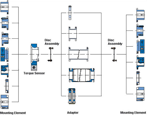
- Figure 4: Combination Possibilities for Couplings
In order to balance axial and angle offsets as well as corresponding lateral offsets, the couplings in principle are offered in a twin-cardanic design.
Requirements such as:
- Compact Design
- Flexible Overall-Length
- High Speed at Short and Long Design
- Small Imbalances
- Creepage Current Isolation
can be implemented, depending on the design of the chosen connection components.
This bearing-free torque sensor-coupling-combination succeeded in combining high dynamics with great flexibility. By this, in addition, a low-cost sensor with short design was originated.
Literature
Holzweißig, F.; Dresig, H.: Lehrbuch der Maschinendynamik
(4. neubearbeitete Auflage). Fachbuchverlag Leipzig-Köln, 1994